Making a clock
30 Dec 2025 · Proof of Concept · ESP32 · 7 Segment Display · NTP
A proof of concept
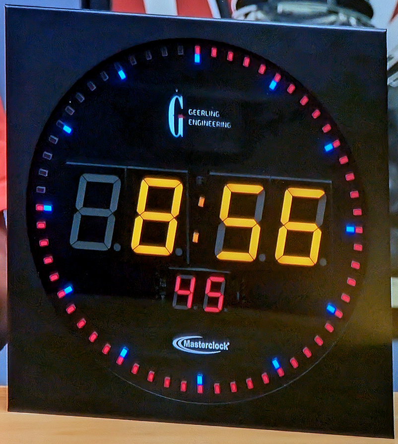
I was watching something on YT the other day and they had a Masterclock CLDNTD12 Digital Analogue Clock onscreen. I'm surrounded by accurate clocks, my phone gets the time from my mobile network provider, my PC displays the time from NTP, my watch displays time from GPS, I've got a raspberry pi hooked up to a GPS antenna that acts as a Stratum-1 NTP server. So I know what time it is. As soon as I saw the Masterclock I was hooked by it's simple and interesting design. I needed one in my life.
v0.1
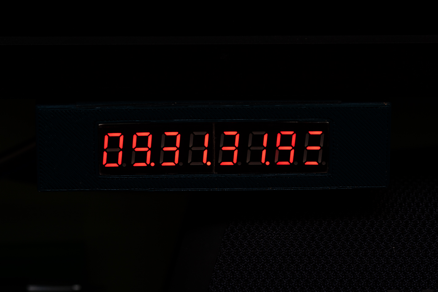
I pulled down a couple of electronics bits boxes and had a root about, I couldn't find what I was looking for so I pointed my browser at ebay and a couple of days later I had what I needed for v0.1 (Proof of Concept).- ESP32-S3 Microcontroller
- 8 Digits of 7 Segment Display on a Max7219 Backboard
- An RTC Module

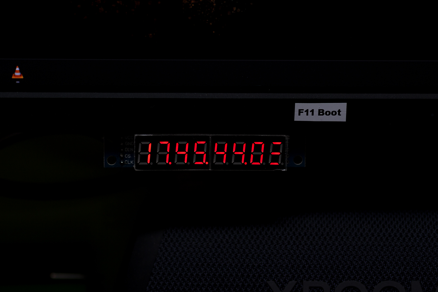
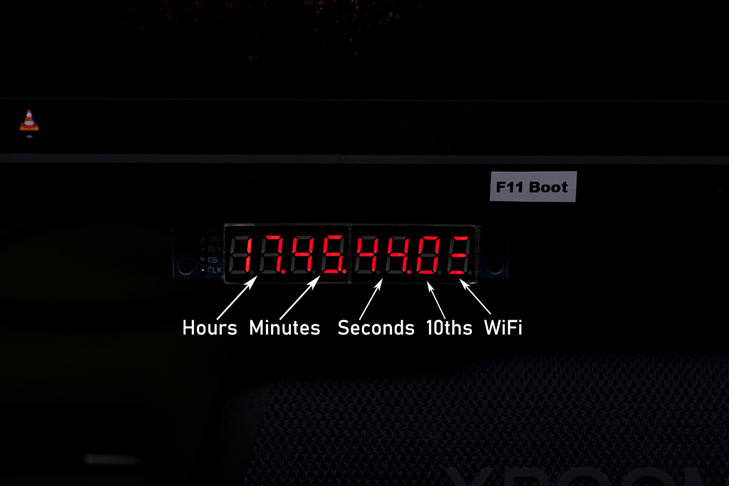
I hooked up the 7 segment displays to the ESP with some jumper wires and wrote a little sketch in Arduino IDE. It interfaces with the MAX7219 which controls the displays, connects to the IoT WiFi and grabs the time, then shows the time on the displays and turns the RSSI into a signal strength, no bars = offline, 1 bar = poor signal, 2 bars = good signal, 3 bars = excellent signal.
It draws 40-42 mA under normal use, the WiFi turns on, grabs the time and turns off every 3 hours, the WiFi is in sleep for the rest of the time allowing the RSSI bars to remain "on screen" and the CPU is down to 80Mhz... my first PC was a 386SX @16Mhz, so 80Mhz is fine for a clock!
V0.2
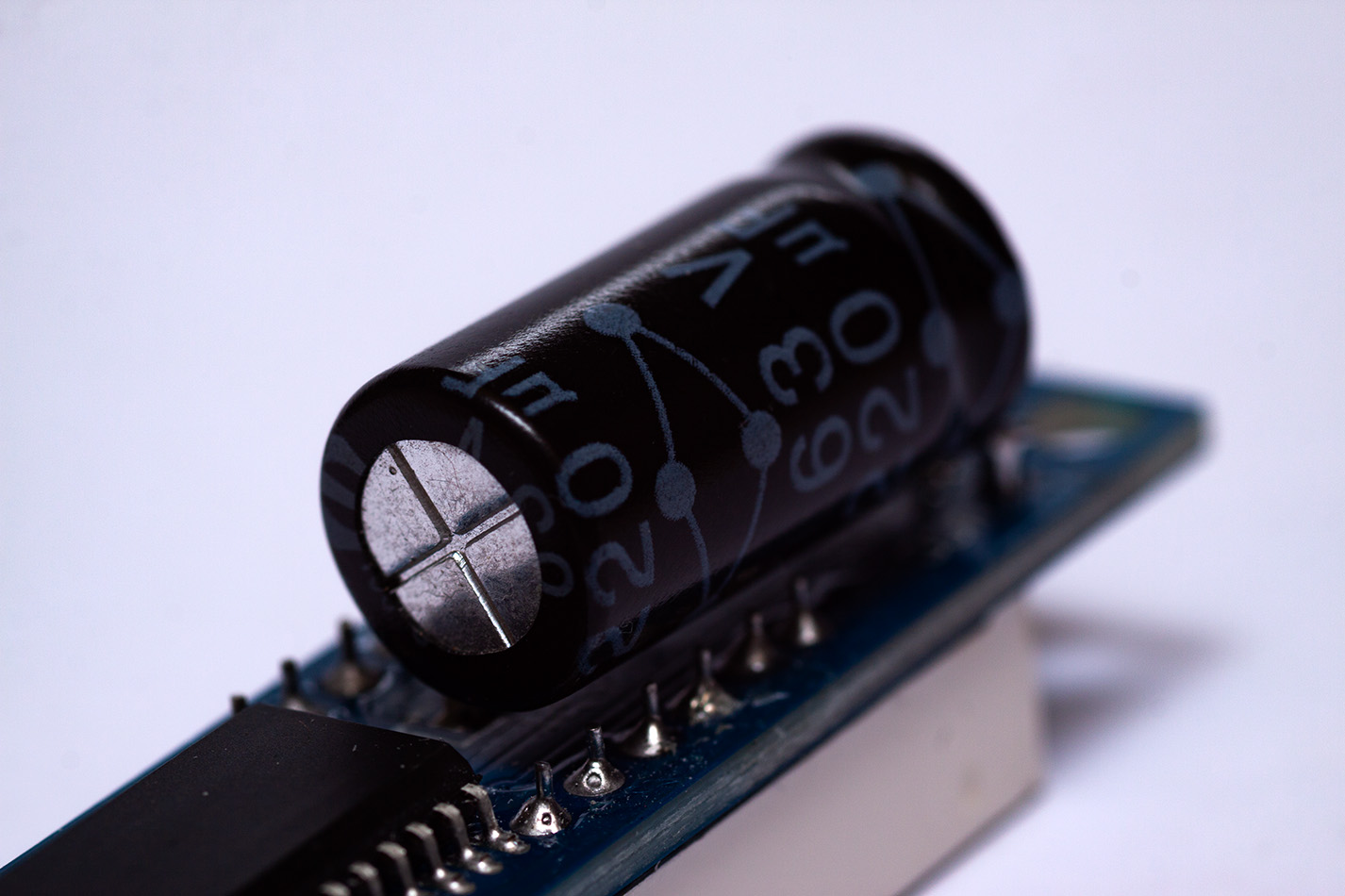
I've added a 220µF capacitor across the VCC & GND pins to stabalise the 5v supply, the tenths counter makes the draw for the LED segments very spiky and without it the display would every now and again go dim or display random segments. A chonky capacitor has solved this and it's worked glitch free for a week or so now.

v1.0
The plan for the v1.0 clock is to get 4 bigger (40-50mm) red 7 segments for the HH & MM markers, with a couple of red dots as colons seperating them. Then 2 15mm (ish) blue or green 7 segments for SS and 2 10mm (ish) blue or green for the 10th of seconds which will sit under the HH MM segments. Round the outside there will be 60 neopixels 1 will come on every second with every 5th one lighting up a different colour. A little OLED screen up top to show the day of the week and IP Address. 6 rectangle LEDs 1, 2, 3 for a WiFi strength indicator.It'll all sit in a 3D printed square case with a circular smoked perspex cover for the display. I'll power it with a USB PSU. I'll be ordering the 7 segments tonight, and I'll put part 2 up here when I've built it. Until then...